A rocket is used to carry a payload into space and making sure this is designed correctly is vital to the success of a space mission. This article will look at what makes up the rocket, how the engine works, and how we use maths skills to do it all.
A rocket is simply a vehicle designed to overcome Earth’s gravity, escape Earth’s atmosphere and carry a payload into space. The payload could be deployed to orbit the earth, or for interplanetary travel and space exploration. Each payload can cost between tens of millions and billions of pounds. Depending on the intended use of each rocket, the look, size, and shape can vary greatly. Rockets can carry a payload mass of between 50kg to 70000kg!
The rocket itself is usually made up of stages, some of which detach as the payload reaches different altitudes to decrease the mass it is carrying to space, each stage is either expendable (lands in the ocean or deserted area of land) or re-usable. Re-usable rockets are becoming more common across the industry (such as the SpaceX Falcon 9), this decreases launch costs and is better for the environment. Single stage rockets require no stage separation and are fully re-usable, although this is hard to achieve as most payloads to be launched are too heavy and current rockets and fuels are not efficient enough to achieve this. Multiple stages are used to reduce the total mass, ejecting empty fuel tanks during launch means less energy/fuel is required to reach space as these empty tanks will not need to be carried by the rocket for any longer than is necessary. The number of stages a rocket needs is dependent on the payload size, mass and how far it needs to travel.
A rocket is made up of 5 key parts, these are;
- Nose Cone – Located at the top of the rocket. Primarily used to punch a hole into the air as it flies, minimising drag and provides stability in flight. This is also where the payload is usually located, this is deployed by the opening of the nose cone once its desired location in space has been reached and releasing of the payload.
- Fins – Located at the bottom of the rocket. Primarily used to minimise drag and provides stability in flight. They can be used to conduct manoeuvres and change direction with input from the guidance system such as rolls and direction changes.
- Guidance System – Located in the rocket body just below the nose cone. This is the brains of the rocket, containing all the electronics and navigation equipment which guides the rocket to its final destination.
- Tanks – Located on the sides or middle part of the rocket. These contain the fuel and oxidiser expended by the rocket during flight.
- Engine – Located at the base of the rocket. The propulsion system that generates the force required to escape earth’s atmosphere and overcome gravity. This uses the fuel and oxidiser contained within the tanks. The engine can be used to conduct manoeuvres in flight by changing the amount of fuel burned to conduct rolls and change direction.
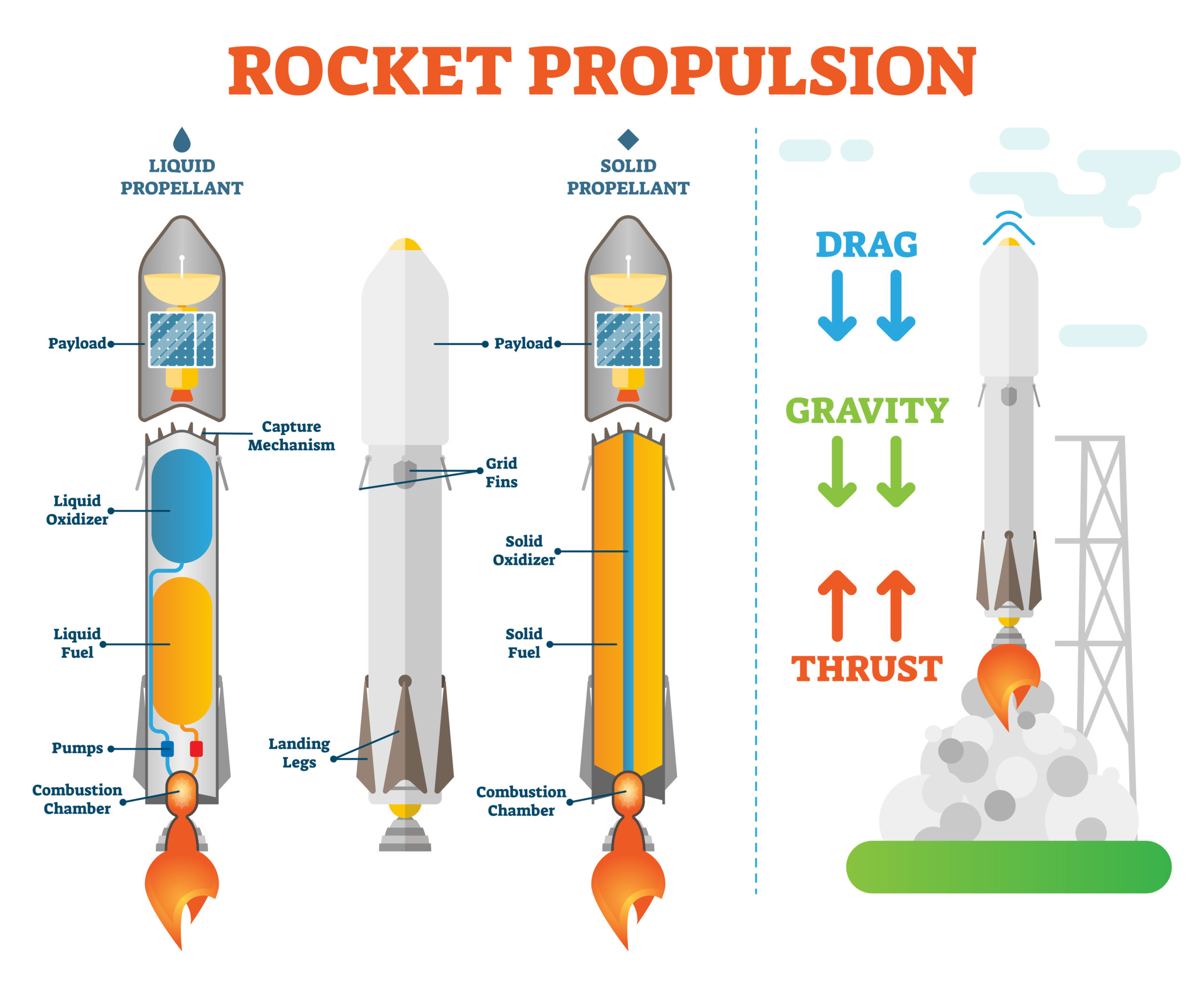
Image: Diagram of the different parts that make up a rocket.
The rocket engine provides the propulsive ‘push force’, also called thrust, that is required to overcome gravity and air resistance. The easiest way to explain how a rocket engine works is to use the fire triangle and Newton’s Third Law. The fire triangle states that 3 ingredients are required for combustion, plus an ignition source.
A rocket needs a fuel to burn for energy, this fuel needs oxygen to keep the fuel burning and heat to increase the burn rate of the fuel. When the fuel and oxygen are combined under heat, a spark or ignition is required and the fire starts, therefore combustion begins. The by-product from this combustion process are the exhaust gases. These exhaust gases provide the energy to the rocket for launch. The exhaust gases are directed in the opposite direction to travel (downwards) to provide the rocket with the propulsive energy (push force) to launch upwards. This propulsive energy generated can be demonstrated through Newton’s Third Law, “every action has an equal and opposite reaction”. Think of a balloon for example, if you let go of a balloon with air in it will fly the opposite way to the air leaving the balloon, the rocket is doing the same thing as the balloon.
The engine is made up of 2 key parts, the combustion chamber and nozzle. The combustion process explained above takes place within the combustion chamber. A combustion chamber is where the oxidiser and fuel are mixed together and ignited, this can reach temperatures exceeding 3,200 °C. Think of this like a furnace where everything is burned. The energy produced from this chemical reaction exits the engine through the nozzle, this is the ‘push force’ where the exhaust gases (big fire trail) are ejected and provides the propulsive energy to push the rocket into space. The exhaust gases exiting the nozzle can leave at speeds exceeding 18,000km/h.
The same principles of how a rocket engine works (according to the fire triangle and Newtons third law above) apply to whatever type of rocket engine that is used. There are four main types that use different types of fuel and oxidiser, these are:
- Liquid engine – A liquid fuel and liquid oxidiser (such as liquid oxygen) are combined from separate tanks into the combustion chamber, they burn according to the explanation above. Once the engine is ignited it can be shut down if necessary. It can provide huge amounts of thrust but is not very efficient.
- Solid engine – A fuel and oxidiser are mixed together into a solid block, this will act as it’s own combustion chamber and be directly connected to a nozzle, the burning of the block will start through the middle of the block. Once the engine is ignited it is difficult to shut down. It can provide huge amounts of thrust but is not very efficient (more efficient than liquid engines).
- Hybrid engine – One of the fuel or oxidiser is a solid and the other is a liquid, these are combined and burn as per the explanation above. Once the engine is ignited it can be shut down if necessary. It can only provide low levels of thrust compared to solid and liquid engines but is quite efficient.
- Electrical engine – These operate through using generated (such as from solar panels) or stored (such as from batteries) electricity to power the engine. One example is the ion thruster where electrons and neutrons collide, ionisation occurs and an electron is ejected from the nozzle with a proton. The engine can be shut off as necessary. Electrical engines are highly efficient but are rarely used in rocket engines, this is because they don’t provide the thrust needed over a short period of time.
So now you know the different parts of a rocket, how a rocket engine works and the different types, how do we go about designing one using maths? There are a number of questions we need to ask ourselves, some of these might be (not a complete list):
- What is the mass of the payload we wish to launch?
- How far do I want my rocket to fly into space to deliver my payload?
- Will our payload be deployed in a particular orbit or be sent to explore a particular area of space?
- Where are we going to launch our rocket?
- What type of engine shall we use?
- What fuels/oxidisers are we going to use?
Once we have answered these, we can start to work out the mass and size of our rocket. The key equation to determine how much velocity change we need to escape earth’s gravity and reach our destination in space that forms the basis of rocket design is shown below using the rocket equation:
∆V=$I_{sp} g_o ln$ ($m_{initial} \over m_{final}$)
- ∆V – this is the change in velocity required to reach our desired destination in space (measured in metres per second).
- Isp – this is the efficiency (specific impulse) of the propellant combination we have chosen. The larger this is the better as it means we can generate more energy from a given amount of fuel. This is a pre-defined value by propellant manufacturers and easy to find on the internet (measured in seconds)
- go – this is standard gravity for earth, this doesn’t change and is a constant number for earth (measured in metres per second2).
- ln ($m_{initial} \over m_{final}$) – this is the natural log of the ratio between the initial launch mass (including propellant) versus the final mass without the expended propellant, an equation to figure this out is the following:
$m_{initial} \over m_{final}$ = $\text{Mass of the Rocket Structure } + \text{ Mass of Propellant } + \text{ Mass of Payload} \over \text{Mass of the Rocket Structure } + \text{ Mass of Payload}$
It is possible to determine through empirical estimation how much mass in propellant and rocket structure (fuel/oxidiser combined) we are going to need based off of our payload mass. We can look at previous rockets with similar payload masses and try to estimate how much propellant and rocket structure we are going to need if the rocket used a similar propellant combination. There is another way to work the mass of propellant required for a given payload mass and ∆V, this can be done if the final destination is known. It is possible to estimate ∆V if we know the exact orbit or end point we wish to reach, we are then able to re-arrange the rocket equation and calculate the ratio between initial and final masses. Finally, using simultaneous equations you can calculate the mass of propellant required.
Once we have worked out the mass of propellant and change in velocity required to get our payload to its desired destination, we can use these values to start designing and sizing the parts of the rocket engine and rest of the rocket. For example, the speed at which the rocket is flying means we may need to design the nose cone to be a certain shape. The materials used for the combustion chamber may need to withstand certain temperatures depending on the propellant combination used and their burn rate required. The nozzle of the engine may need to eject the exhaust gases at a certain speed to achieve the estimated ∆V, meaning the nozzle needs to be a certain shape/size to achieve this. There are many more design decisions that are dictated by the ∆V, mass of propellant etc, these are just a few examples.
Daniel English
MEng ASEP, Systems Engineer, Expleo Group – Electrical and Embedded Systems (UK)

Download PDF
If you wish to save, or print, this article please use this pdf version »
Learning resource
We have created learning notes to assist students and educators to further investigate the topics covered in this article. You can download the learning resource here »
